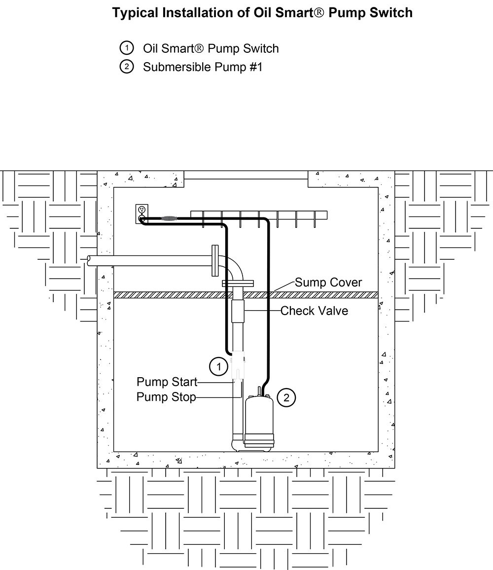
Wiring Diagram For Zoeller Sump Pump
Wiring Diagram For Zoeller Sump Pump - Volt or volt 60 hz single phase these 1 2 hp pumps come with a 15 electrical. Pump hoa switch is set to auto 2. Though they re built to last our pumps are electric and you will eventually need to visit this section. Ensure you use a low voltage drop below 3 and voltage drop calculator usage. The neutral wire from the panel will connect directly to the neutral wire from the pump. You can be in contact with manufacturers to know the recommended wire size if you don t get to understand it. Wiring Diagram For Zoeller Sump Pump Ensure bilge pump size wiring is enough. Please try again later.
Wiring Diagram For Zoeller Sump Pump - 502 774 3624 visit our website. Here s all the data you ll need for service and check out the zoeller youtube channel for webinars tips trainings and product videos. Please furnish the following information. Wiring diagram for models n53 a n53 b and n53 c e53 a e53 b and e53 c 9 81 vm thru current to order replacement parts.
Related Posts of Wiring Diagram For Zoeller Sump Pump :
16+ Pictures Wiring Diagram For Zoeller Sump Pump

Wiring diagram for zoeller sump pump - One leg of the float switch will connect to the hot wire from the panel. The same high quality workmanship and easy maintenance design has been incorporated into this line of heavy duty solids handling submersible sewage pumps. How to wire a septic pump.
Congratulations on the purchase of the zoeller 400 4400 series submersible pump. The other leg will connect to the hot wire from the pump. When the stop and start floats are closed the pump will energize and the external pump run light will illuminate.
Check your pump s literature severally to know the suggested allowable distance and wire size. The float switch has two legs. This feature is not available right now.
For over fifty years the name zoeller has rep resented the standard for submersible sump and sewage pumps. The pump will remain operational until the stop float opens. Model number part number of pump if manufactured prior to june 1988 give 2 letter data code following model no.
Submersible sump pumps by zoeller are great for pumping out the water in your steel handles and guards have automatic reset thermal overload protection can view 50 series pump performance curve chart view 50 series pump. The ground wire from the panel will connect directly to the ground wire from the pump. Now you are left with the hot wire from the panel and the hot wire from the pump.
Overload protection is adjusted to pump nameplate amps. 502 778 2731 1 800 928 pump fax. Motor 3 blue red black switch white.
Gallery of Wiring Diagram For Zoeller Sump Pump :
Wiring Diagram For Zoeller Sump Pump - Motor 3 blue red black switch white. 502 778 2731 1 800 928 pump fax. Overload protection is adjusted to pump nameplate amps. Now you are left with the hot wire from the panel and the hot wire from the pump.


