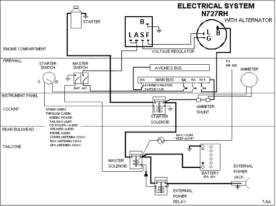
Hartzell Alternator Wiring Diagram
Hartzell Alternator Wiring Diagram - Connect the output cable see cable sizing recommendations below ground field wire stator tach wire if needed and other necessary wiring. With key on power is then transferred through the no charge indicator light to the 1 spade on the alternator regulator connection. Information includes a description and operation of the propeller installation and removal instructions testing and troubleshooting information inspection and check and maintenance practices information. This diagram shows the simple wiring diagram for negative ground delco si series alternators the ignition switch is most commonly powered from the starter battery stud but source may vary depending on application. Visit hartzell engine. Download the most current installation instructions for the following aircraft alternator models. Hartzell Alternator Wiring Diagram We are hartzell engine technologies. The red wire is the current supply from the bus that powers the voltage regulator.
Hartzell Alternator Wiring Diagram - Some shimming or modification to the alternator mount may be required to assure proper alignment. Plane power alternator wiring diagram interav alternator wiring diagram new hartzell alternator wiring diagram below is a picture a plane. Through our brands we offer aircraft engine accessories and cabin heating solutions for manned and unmanned fixed and rotary wing aircraft powered by piston turboprop and turbofan engines. Hartzell owner s manuals provide instructions for continued airworthiness ica.
Related Posts of Hartzell Alternator Wiring Diagram :
18+ Images Hartzell Alternator Wiring Diagram

Hartzell alternator wiring diagram - Hartzell engine technologies asg series alternator new asg series alternators were originally developed by aero electric and are oem on several cessna applications and pma replacements for out of production 24v ford alternators. Family model number manual type pdf. Twin engine wiring diagram.
The yellow wire is the field wire that connects to the alternator s f1 terminal. And connect the red wire to the output side of the alternator 10 32 stud take the long wire and connect to the side of the coil. Figure 2 1 alternator simplified electrical diagram 2 1 figure 2 2 stator wiring diagram typical 2 2 figure 2 3 typical alternator cutaway basic components 2 3 figure 2 4a es 10024 front view 2 5.
Hartzell engine technologies llc 2900 selma highway montgomery al 36108 usa. The orange wire connects to b. To open pdf documents the free adobe reader is required.
The orange wire and the black wire are used to sense alternator voltage directly from the b terminal and ground connection at the alternator. Single engine internally regulated wiring diagram. Connect alternator to balmar regulator wiring harness as indicated in wiring diagram included on page 12.
And we are a leading manufacturer in general and military aviation.
Gallery of Hartzell Alternator Wiring Diagram :
Hartzell Alternator Wiring Diagram - And we are a leading manufacturer in general and military aviation. Connect alternator to balmar regulator wiring harness as indicated in wiring diagram included on page 12. Single engine internally regulated wiring diagram. The orange wire and the black wire are used to sense alternator voltage directly from the b terminal and ground connection at the alternator.


