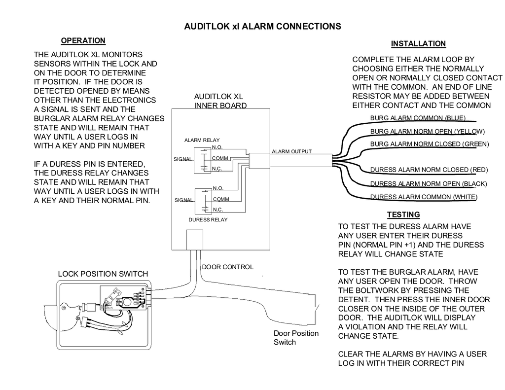
Duress Alarm Wiring Diagram
Duress Alarm Wiring Diagram - Wire is an output for door ajar forced entry and time. Reset encryption key to factory default. Auto page rf 350 rs manual 1 auto page 2 wiring diagram. Connect the ring terminal end of the strap under one of the plate screws between the plate and the wall see fig. Door time out alarm intrusion alarm duress alarm and tamper alarm anti pass back multi door interlock multi card open support 128 efficient time and holiday schedules. The alarm consists of 3 normally open push button switches which can be hidden or in plain view. Duress Alarm Wiring Diagram This information provides further details relating to the installation and operation standards of university intrusion and duress alarm systems on california state university northridge property. The duress code can be entered when the ring alarm is in any mode.
Duress Alarm Wiring Diagram - This is a 3 zone alarm for use in high risk areas or possible duress situations. The spdt circuit and the latching led circuit. University intrusion and duress alarm installation operation standards i. 95 325 97 328 manuals.
Related Posts of Duress Alarm Wiring Diagram :
19+ Images Duress Alarm Wiring Diagram

Duress alarm wiring diagram - Indicating appliance circuits connect the fire alarm panel to the components which alert building occupants of the fire i e bells horns speakers strobe lights etc. The wiring diagrams show two separate circuits. Connect the wire end of the strap to the negative power supply connection of the keypad the black wire.
Rely on sti. Even if the alarm is already disarmed entering the duress code and pressing disarm will send the duress signal. Typical examples being banking or betting booths.
Choosing a duress code. Tamper alarm 8 7 tamper back up battery enclosure tamper connection general alarm trouble alarm duress alarm c no nc c no nc c no nc c no nc hirsch mx controller ethernet sw 1 sw 2 sw 3 on on switch bank 2 s1 s2 3 s4 off secure encryption key. Sti is a specialist manufacturer of fire safety and security products.
And black wire and is included with all 6500 series keypads. Once pressed the alarm will latch and a led will light showing which zone has pressed the alarm. The latching led must be powered and controlled by respectively a 12 vdc source in the alarm panel 24 hour switchable power loop or equivalent and a normally closed push button or spring loaded momentary.
Download car alarm installation manual of auto page rf 350 rs for free. The duress code cannot be the same as any other owner or user access code and must have at least 2 digits that are different. The following illustrations show schematics wiring connections riser diagram and wire pull for some commonly used fire alarm circuits.
Our products help deter false alarms and prevent theft and vandalism of smoke detectors fire extinguishers and other essential fire and security equipment. On on master first controller. This wiring diagram refers to the stock bmw wiring if you need it for reference.
Gallery of Duress Alarm Wiring Diagram :
Duress Alarm Wiring Diagram - This wiring diagram refers to the stock bmw wiring if you need it for reference. On on master first controller. Our products help deter false alarms and prevent theft and vandalism of smoke detectors fire extinguishers and other essential fire and security equipment. The following illustrations show schematics wiring connections riser diagram and wire pull for some commonly used fire alarm circuits.


